Polymer Based Nano Composites Reinforced By Magnetic and Dielectric Particles for Radar Absorbing Applications
Saba Esmaeili
Published Date: 2022-04-12DOI10.36648/2471-9838.8.3.66
Saba Esmaeili*
Department of Physics, Urmia University, Iran, Islamic Republic
- *Corresponding Author:
- Saba Esmaeili, Department of Physics, Urmia University, Iran, Islamic Republic;Tel: 989144398380; E-mail: s.esmaeili@urmia.ac.ir
Received date: March 14, 2022, Manuscript No. IPNTO-22-12206; Editor assigned date: March 17, 2022, Pre QC No. IPNTO-22-12206 (PQ); Reviewed date: March 31, 2022, QC No. IPNTO-22-12206; Revised: April 5, 2022, Manuscript No. IPNTO-22-12206(R); Published date: April 12, 2022, DOI: 10.36648/2471-9838.100061
Citation: Esmaeili S (2022) Polymer Based Nano Composites Reinforced By Magnetic and Dielectric Particles for Radar Absorbing Applications. Nano Res Appl Vol:8 No:2
Abstract
Three samples of MWCNT-based Nano-composites with different filler combinations were prepared by means of solution blending and adding epoxy resin and hardener in x- band standard size of 22.8 × 10.1 mm2 with 2 mm thickness and 20% weight ratio. In order to observe the maximum absorption, combination of dielectric, magnetic losses and proper conduction by fillers (MWCNT, TiO2, Fe3O4 and Poly aniline (PANI) has been used. In third sample, TiO2 by sol-gel method was coated on MWCNT (TiO2@MWCNT). Phase and morphology features were investigated by X-ray diffraction analysis and Scanning electron microscopy. Nano- composites microwave features were studied on X- band with range of 8-12 GHz. Nano- composite reflection loss in RAM-Fev4/PANI/MWCNT has three minimum peak amounts with -22.92 dB at 10.06 GHz; -19.26 dB at 9.46 GHz and -18.41 dB at 10.78 GHz. RAM-Fe3O4/PANI/TiO2/MWCNT has one minimum peak amount which includes -18.26 dB at 10.18 GHz. in addition, RAM-Fe3O4/PANI/TiO2 coated MWCNT has one minimum peak amount which includes -40.02 dB at 9.88 GHz.
Keywords
Radar absorber material; X-Band; Reflection loss; Loss tangent; Scattering matrix
Introduction
In modern world, the problem of electromagnetic interference has become more serious due to wide applications of electromagnetic waves in GHz range for mobile phones, radar systems and so on. Therefore, the demands to develop more economical electromagnetic wave absorbers with wider absorbing bandwidths and more effective absorbing are ever increasing. With development of Nano technology, microwave nano absorbers playing an important role as a new generation of electromagnetic absorbers. High frequency band, low density and low thickness are main features for mentioned absorbers [1,2]. Radar Absorbing Materials (RAM) absorbs energy from the electromagnetic fields passing through them. RAM dissipates the absorbed electromagnetic energy into heat. Since electromagnetic wave has an electric and magnetic component, it is common to separate dielectric and magnetic absorption mechanisms. In order to obtain combination of dielectric and magnetic losses, Radar absorber materials include polymeric matrix and fillers such as carbon, titanium dioxide, iron particles and conductor polymer [3,4]. These radar absorber materials called hybrid matrix which they have electric and magnetic fields weakness simultaneously.
Multi-walled carbon nanotubes due to excellent electrical conduction, high ratio, well thermal stability, resistance against chemical agents and low density are common choices [5].Multi-walled Carbon Nanotubes have a number of free electrons in their structure, thus absorbing energy and contributing to the distribution of most of the material in the matrix. In addition the higher surface area is the reason for the better absorption of the microwave. Titanium dioxide is a semi–conductor [6]. The size of the particles is much smaller in nano titanium dioxide. Hence, they are more capable and effective. The characteristics of the nano titanium dioxide can be known as high dielectric stability, high thermal stability and quantum size effect. Titanium dioxide helps the microwave absorption with low band gap energy. Poly aniline is one the earliest synthetic polymers that have attracted because of high electrical conductivity [7]. Poly aniline is used for the reason that of easy fabrication, soluble, favorable properties for absorbers, well thermal stability and low density. Ferrites due to characteristics such as high electrical resistance, stable material in high temperature, low toxic percent, reversible spinel structure and high amount of magnetic saturation are considered [8]. Nano ferrites with their special nature and crystal structure (spinel structure) are hard ferromagnetic due to exchange coupling effect as they have large hysteresis loop. These materials have excellent dielectrics and magnetic features and they are suitable item for electromagnetic absorber materials, but they are heavy and costly. Thus, polymers are used as polymeric matrix because of light weight, cheapness and flexibility and materials added to their matrix only as fillers [9].
On the other hand, polymers themselves operate as an absorbing component in the composition of polymer composites. For example, the hybrid epoxy resin matrix contributes and improves the microwave absorption properties. The combination of polymer composites with low density, low thickness and high bandwidth are the maximum loss of electromagnetic waves. Moreover, polymer composites play an important role in particle size reduction. The interesting properties of polymers such as low weight, Non-erosion, mechanical tension and electrical adjusting influence them to interact with the optical and magnetic compatibility of nanoparticles. Radar absorber material mechanism depends on proper impedance between electric and magnetic materials [10]. The objective of this study is to produce and characterize polymer based composites reinforced by magnetic and dielectric particles for radar absorbing applications. In order to achieve this, three samples of hybrid matrix epoxy- nano composite materials are investigated which includes Fe3O4/PANI/MWCNT, Fe3O4/PANI/TiO2/MWCNT and Fe3O4/PANI/TiO2@/MWCNT. Blending of these materials with different shape and particles size can generate multiple dispersion with creation of electromagnetic losses in thermal form. Also dipole, interaction and ionic conduction are other mechanisms in radar absorbers. 20% wt. fillers was dispersed in 80% wt. epoxy resin matrix and also Nano composites with 2 mm thickness were prepared with observed optimized results.
Materials and Methods
EquipmentBy utilizing non-mono-chromated MgKa radiation as the excitation basis, X-ray Diffraction (XRD) shapes were documented on an X’pert Philips X-ray photoelectron spectrometer. In order to study the morphology of samples employing scanning microscopy with SEM (TESCAN MIRA3), samples were dispersed in DMF and then dried on a silicon wafer. By utilizing first fracturing in liquid Nitrogen, the images were taken. With the intention of measuring the network parameters of microwave networks, a network analyzer was used. This is used for X-band frequency of 8 to 12 GHz and the test were conducted using 2 mm concrete specimens with size of 22.8 × 10.1 mm2.
MaterialsThe Aniline was purchased from Merck and distilled under reduced pressure before use to prepare polyaniline. The MWCNT were purchased with 20-30 nm external diameter and 3-15 μm length. The Tetra-n- butyl orthotitanate was purchased from Merck for synthesis TiO2 coated MWCNT. FeCl2, FeCl3 and Ammonia 25% were purchased for synthesis of Fe3O4. The Epoxy resin, diglycidyl ether of bisphenoal A (LY556) and the hardener, Jeffamine were purchased to prepare nanocomposite.
Synthesis of Fe3O4In order to prepare Fe3O4 nano powder with co-precipitation method and in accordance with report, Aqua pura (100cc) degassed by N2 for 20 minutes in reaction region. Then FeCl2 and FeCl3 salts mixed with 1:2 molar ratios and Mixing solutions with magnetic stirrer at 80°C. Next step is to add Ammonia 25% (10cc) to solution. Reaction continued for 45 minutes and Fe3O4 powder washed aqua pura and dried [11].
Synthesis of Poly anilineFor the purpose of poly aniline preparation; 25 mL of Aniline dissolved in 500 mL Acid chloric 2 molar in ice bath. Then Dropping the 250 mL Ammonium persulphate 2 molar solution with magnetic stirrer until to obtain polymerization reaction. Monomers will transfer to polymers within one hour [12]. To separate non-react monomers, this is washed by 500 ml Hydrochloric acid. The sample stayed at room temperature for 48 hours and heat treatment at 60°C-70°C for 1 hour.
Chemical modification of MWCNTThe first stage of MWCNT to receive TiO2 relates to agent factor. Nitric acid and sulfuric acid (HNO3 and H2SO4) were used with 2:3 ratios [13]. Combination of acid, MWCNT and magnetite placed on heater string tool and under 50°C for duration of 24 hours. This then dried under 100°C after cleaning with pure water.
Preparation of TiO2 coated MWCNTIn the second stage of agent MWCNT, titanium (IV) n-butoxide, Isopropanol and pura water were used with 1:0.3:50:25 weight ratio [14]. Agent MWCNT with isopropanol solution was placed on ultrasonic bath for 30 minutes. Then, titanium (IV) n-butoxide was added to materials and it was placed on sonic bath for 15 minutes. Pura water was added to materials while stirring the blend for 48 hours under room temperature. Isopropanol was heated and solution dispersion was carried out under 100°C. Finally, powder was placed on furnace under 500°C for 100 minutes (Figure 1).

Figure 1: Construction steps of TiO2 coated MWCNT nano composite.
After preparation of fillers and construction of nano composites (20% wt fillers+80% wt epoxy resin) by solution blending method, MWCNT, Fe3O4 and Polyaniline were ultrasonicated in ethanol solution with ultrasonic bath and under 60°C for 30 minutes. During last epoxy resin for added materials ultrasonic bath has been used for 60 minutes. Then solution dispersion was performed under 40°C for 18 hours [15,16]. At the last stage and in order to cure, hardener was added to system in proper frame with XR 90 waveguide shim opening by 22.8 × 10.1 mm2 and 2 mm thickness under usual climate conditions for 48 hours (Figure 2).

Figure 2: Solution blending method.
Fe3O4/Pani/TiO2/MWCNT nano composite construction is similar to previous sample apart from adding TiO2 tofiller during sonication stage. To construct Fe3O4/Pani/TiO2@/MWCNT nano composite, TiO2@MWCNT was acted in filler sonic stage for construction of previous two nano composites (Figure 3).

Figure 3: Three samples of hybrid matrix nano composite materials.
Results and Discussion
Characterization of FillersScanning electron microscopy depicts only the surface morphology or surface structure. Figure 4 shows SEM images for Fe3O4, PANI and TiO2@MWCNT particles. Figure 4 a shows SEM images for Fe3O4 particles with size of 21.57 nm, 31.76 nm and 26.09 nm. One of the effective factors in nano ferrites natural resonance is particles size minimization, which causes creation of better behavior in GHz range. In the Figure 4 a, a series of discrete particles are uniformly observed which have more traps.These are impeding the conductivity. Figure 4 b shows SEM images of PANI particles 25.22 nm, 27.94 nm and 25.82 nm. The surface of poly aniline spheres is uniform. Ploy aniline spheres are very soft and far away from any impurities. As seen in the Figure 4 b there is more group particles that can cause electrical current transmission more easily. As a result, these particles exhibit higher conductivities. Figure 4 c shows SEM images of TiO2@MWCNT particles size of 21.74 nm, 27.03 nm, 28.43 nm and 31.25 nm. Adjustment of surface morphology by modification of surface multi-walled carbon nanotubes with titanium dioxide is achievable.
Surface morphology shows TiO2 homogenous covering on MWCNT. Generally, various particles with anisotropic shape and size for nano composites are main effective factors in generation of different anisotropy field. This can cause rise in absorption frequency bandwidth. Particles size rising from surface area, rising atoms surface and multiple reflection are as effective factors in increasing dielectric and magnetic losses, which they cause to rise in electromagnetic waves absorption.

Figure 4: SEM images of (a) Fe3O4, (b) PANI and (c) TiO2 coated MWCNT.
With X-ray diffraction, information about the structure, material and the value of the elements can be obtained. The most useful template for using XRD is to compute the grain size and strain broadening with the Williamson-Hall method.
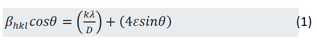
Where β is the full width of half maximum (FWHM) of the XRD line, θ is peak position, k is a constant equal to 0.94, λ is the X-ray wavelength, D is the particle size and ε is the strain broadening. Therefore, by using the Williamson-Hall method, the size of the particles and the strain broadening are calculated for both Fe3O4 and TiO2 @MWCNT (Table 1). It is to be noted that geometric parameters for the poly aniline sample due to amorphous structure was not calculated. The results show a bit difference with the scanning electron microscope, which in turn indicates the approximation of the Williamson-Hall method.
Table 1: Geometric parameters of Fe3O4 and TiO2@MWCNT.
| Sample | D (nm) | ε no unit |
|---|---|---|
| Fe3O4 | 16.5 | 1.0238 |
| TiO2@MWCNT | 43.9 | 0.0239 |
The phase purity of the samples was confirmed by X-ray diffraction analysis (XRD) and the pattern is shown in Figure 5 for 2 θ ranging from 10° to 80°. Poly aniline is an amorphous structure. The formation of crystal spheres is confirmed in its structure due to presence of peaks in 2 θ=16.73°,19.79°,25.39°,33.75° and 35.64°. In general, XRD analysis shows amorphous structure of poly aniline. The Fe3O4 has a face-centered cubic structure. Characteristic peaks were observed in the XRD pattern at 2 θ of 30.19°, 35.56°, 43.22°, 53.62°, 57.16° and 62.77°corresponding to the diffractions of 220, 311, 400, 422, 511 and 440 crystal faces of Fe3O4 spinel structure. Miller indices are determined by JCPDS cards. For TiO2@MWCNT, multiple peaks were created against TiO2 standard state with octahedral form. Characteristic peaks were observed in the XRD pattern at 2 θ of 25.3°, 37.82°, 48.02°, 53.91°, 55.04°, 62.69°, 68.79°, 70.26°and 75.06° corresponding to the diffractions of 101, 004, 200, 105, 201, 204, 116, 220 and 215 crystal faces of TiO2@MWCNT structure. Severe peaks create in 25.38° which are equal with (101) and XRD sample and this is confirmed by previous reports [14]. Coordinated peaks with octahedral form confirm TiO2 on MWCNT generation during Sol gel coating process.

Figure 5: XRD analysis of fillers.
In order to investigation features of electromagnetic samples, scattering parameters called scattering matrix must be observed. The scattering matrix is the mathematical concept that fully describes the propagation of an electromagnetic wave through a multi-port network. Vector Network Analyzer (VNA) is set up to measure the S-parameters of a device under test. The Vector network analysis was calibrated by the Thru-Reflect-Line (TRL) calibration waveguide method, X11644 A, for X-band method, in order to measure the transmission and reflection characteristics of the surface of the absorbing sample by the device (Figure 6).

Figure 6: Measurement setup.
The Nicolson Ross Weir (NRW) model was used to determine samples electromagnetic features [17]. The Nicholson-Ross model is way to calculate permittivity and permeability [18]. It utilizes all four S-parameters to calculate permittivity as well as permeability. Features of microwave material absorber can be estimated by magnetic and dielectric cases such as complex permittivity ε=ε^ (' )-iε^" and complex permeability μ=μ^'-iμ^". Where ε^ (' ) is real permittivity; ε^" is imaginary permittivity; μ^' is real permeability and μ^" is imaginary permeability. Therefore, complex permittivity and permeability of epoxy composites in 8-12 GHz range has been investigated.

Figure 7: Real permittivity of nano composites.
Figure 7 shows real part of permittivity. RAM-Fe3O4/PANI/MWCNT, RAM-Fe3O4/PANI/TiO2/MWCNT and RAM-Fe3O4/PANI/TiO2@MWCNT are in 5.09-5.28, 4.64-5.7 and 5.41-5.81 range respectively. They are constant approximately in 8-12 GHz range but with low fluctuation. In metal-insulator composites, polarization and space charge can be investigated in fluctuation regions with dipolar cases [19].

Figure 8: Imaginary permittivity of nano composites.
Figure 8 shows imaginary part of permittivity. RAM-Fe3O4/PANI/MWCNT, RAM-Fe3O4/PANI/TiO2/MWCNT and RAM-Fe3O4/PANI/TiO2@MWCNT relate to range of 0.91-1.22, 0.61-0.97 and 1.19-1.38 respectively. Polarization mechanism helps with materials dielectric function, which they observe in direction of microwave frequency polarization range and space charge polarization. Complex permittivity of the third sample is more than the others.

Figure 9: Real permeability of nano composites.
Figure 9 shows real permeability of nano composites. RAM-Fe3O4/PANI/MWCNT, RAM-Fe3O4/PANI/TiO2/MWCNT and RAM-Fe3O4/PANI/TiO2@MWCNT are in range of 0.95-1.12, 0.94-1.13 and 0.99-1.16 respectively. Figure 10 shows imaginary permeability of nano composites.RAM-Fe3O4/PANI/MWCNT,RAM-Fe3O4/PANI/TiO2/MWCNT and RAM-Fe3O4/PANI/TiO2@MWCNT relate to range of 0.02-0.03, 0.01-0.02 and 0.01-0.05 respectively.
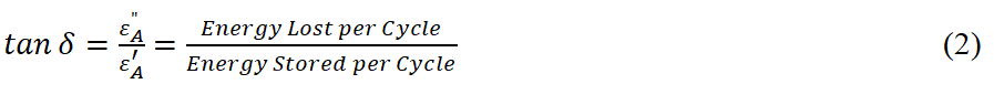

Figure 10: Imaginary permeability of nano composites.
Weak peaks were observed in Figure 10 and this can be described with natural resonance and exchange resonance. Line fluctuations resonance frequencies are observed with effective heterogeneous field which they depend on crystal, magnetic particles geometry, particles size heterogeneous and magnetic particles interaction. Exchange energy and size effect have qualitative relation with exchange resonance. Generally natural resonance and exchange resonance coexistence are important for large bandwidth as microwave absorber [20]. Fe3O4 particles are the cause to eddy circuit loss as well as hysteresis and magnetic losses [21].
Loss tangent describes a dielectric material's inherent dissipation of electromagnetic energy. This is shown in Figure 11 for the composites. As seen in the figure, dielectric loss of the third sample with the presence of TiO2 @ MWCNT is more than other samples, which indicates the more absorption rate.
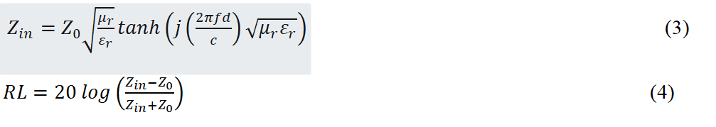

Figure 11: Loss tangent of nano composites.
According to Transmission line theory the reflection loss of electromagnetic waves of the nano composites can be calculated (Figure 12) [22].
Where Z0 is air characteristic impedance 377, μ_(r),ε_r are the relative compelx permeability and permittivity of the materials, f is the microwave frequency in Hz, d=0.002 is thickness of the absorber in m, and c is the velocity of light in free space in (m/s). Figure 12 shows hybrid nano composites reflection loss for X band in 8-12 GHz. Fillers amount and materials blending direct effect on microwave absorber features can be observed.

Figure 12: Reflection loss of nano composites.
In this figure, reflectivity peaks position changes with higher or lower fillers frequency. In RAM-Fe3O4/PANI/MWCNT composite reflection loss under -10 dB (90% absorption) is nearly 0.26 GHz in 8-8.26 GHz range and also it is nearly 3.8 GHz in 8.56-12.37 GHz. -22.92 dB minimum amount relates to 10.06 GHz. When TiO2 added to Nano composite fillers it can be said that in RAM-Fe3O4/PANI/TiO2/MWCNT composite reduction of microwave absorption peaks against previous composites according to Figure 12. For RAM-Fe3O4/PANI/TiO2/MWCNT composite, reflection loss under -10 dB is nearly 0.54 GHz in 9.88-10.42 and close to 1.02 GHz in 10.87-11.89 GHz range. -18.28 dB minimum amounts relate to 10.18 GHz. In third composite, by changing fillers dispersion from TiO2 to TiO2@MWCNT peaks microwave absorption increases significantly. In third composite with RAM-Fe3O4/PANI/TiO2@MWCNT reflection loss under -10 dB is nearly 0.49 GHz in 9.5-9.99 GHz and it is nearly 0.14 GHz in 10.34-10.48 GHz range. This nano composite minimum amount is equal to -40.02 dB in 9.88 GHz. The main point relates to three kinds of composites with minimum amount around 10 GHz. In third sample with the presence of TiO2 @ MWCNT Migrating electrons, space charge polarization and interfacial polarization have more effect. Table 2 expresses microwave absorber features for three composites. Absorber bandwidth and absorption amount of fillers were affected by fillers dispersion method.
Table 2: Microwave absorption properties of samples.
| Frequency range (GHz) (RL<-20) | Frequency range (GHz) (RL<-10) | Fm (GHz) | RLm (dB) | sample |
|---|---|---|---|---|
| 9.97~10.12 | 8~8.26/8.56~12.37 | 10.06 | -22.92 | Fe3O4/PANI/MWCNT |
| 0 | 9.88~10.42/10.87~11.89 | 10.18 | -18.28 | Fe3O4/PANI/TiO2/MWCNT |
| 9.85~9.92 | 9.5~9.99/10.34~10.48 | 9.88 | -40.02 | Fe3O4/PANI/TiO2@MWCNT |
The performance of radar absorbing materials depends on many factors. This can be listed as; production/synthesis method, filler type, grain size, loading level, types of polymer matrix, physical thickness of the sample. Each particle with anisotropy shape and size inside nano composite generate different anisotropic fields and it relates to increasing absorbed frequency bandwidth [23]. On the other hand, more surface area and multiple reflections in nano fillers generate dielectric and magnetic losses [24]. These phenomena are suitable for more absorption in microwaves. Nano meter particles have quantum size, surface and tunneling effects. They are yhe cause of rise in absorber bandwidth more than -10 dB [25,26]. Another factor to describe in nano composites microwave behavior relates to particles frontier width, which by decreasing particles size, the frontier width was increased. In addition, coupling interaction is increased in frontier width and surface area causes to increase in dipoles generation and microwave features [27].
Conclusion
Three hybrid Nano composite samples with 2 mm thickness and 20% weight fillers (80% weight epoxy resin) were prepared after successful fillers synthesis. The fillers were characterized by XRD and SEM. Complex Permittivity, complex permeability and loss tangent spectrum were prepared in 8-12 GHz ranges. In addition, microwave features were investigated for RAM-Fe3O4/PANI/MWCNT, RAM-Fe3O4/PANI/TiO2/MWCNT and RAM-Fe3O4/PANI/TiO2@MWCNT composites with minimum amounts of -22.92 dB at 10.06 GHz, -18.28 dB at 10.18 GHz and -40.02 dB at 9.88 GHz for samples respectively. The results indicate peak frequency for three samples around 10 GHz. TiO2 existences by dielectric loss caused in increasing of absorption.This case was happened in third composite with TiO2@MWCNT. Therefore, proper blending of absorber dielectric and magnetic losses are effective for features optimization.
Compliance with ethical standards, Conflict of interest the author declares that she has no conflict of interest.
References
- Ni QQ, Zhu YF, Yu LJ, Fu YQ (2015) One-dimensional carbon nanotube@polyaniline multi hetero structures for microwave absorbing application. Nanoscale Res Lett 10:174
- Qing Y, Yang Z, Wen Q, Luo F (2016) CaCu3Ti4O12 particles and MWCNT-filled microwave absorber with improved microwave absorption by FSS incorporation. App Phy A 122:1-8
- Esmaeili S, Sedghi H (2019) Absorption properties of TiO2 coated MWCNT/Fe3O4/polyaniline Nano composite in X-band. IJET 8:102-109
- Zeng Z, Chen M, Jin H, Li W, Xue X, et al. (2016) Thin and flexibe multi-walled carbon nanotube/waterborne polyurethane composites with high-performance electromagnetic interference shielding. Carbon 96:768-777
- Bhattacharya P, Sahoo S, Das CK (2013) Microwave absorption behavior of MWCNT based nanocomposites in X-band region. Expr Poly Let 2:212-223
- Huang X, Kun J, Liu X (2015) Titanium dioxide/Multi-Walled Carbon Nanotube heterostructure containing single one carbon nanotube and its electromagnetic properties. Worl Scie 10:1550102
- Zhao J, Lin J, Xiao J, Fan H (2015) Synthesis and electromagnetic, microwave absorbing properties of polyaniline/graphene oxide/Fe3O4 nanocomposites. RSC Adv 5:19345-19346
- Zhu YF, Ni QQ, Fu YQ, (2013) NatsukiT Synthesis and microwave absorption properties of electromagnetic functionalized Fe3O4-polyaniline hollow sphere nanocomposites produced by electrostatic self-assembly. J Nanopart Res 15:1988-1989
- Dias JC, Martin IM, Rezende MC (2012) Reflectivity of hybrid microwave absorbers based on NiZn ferrite and carbon black. J Aerosp Technol Manag 4:267-274
- Esmaeili S, Sedghi H (2019) Radar absorbing materials mechanism and effective parameters in behavior improving. IJRTE 1955-1959
- Li X, Han X, Tan Y, Xu, P (2008) Preparation and microwave absorption properties of Ni-B alloy-coated Fe3O4 particles. J Alloys Compd 464:352-356
- Zhang D, Karki AB, Rutman D, Young DP, Wang A, et al. (2009) Electrospun polyacrylonitrile nanocomposite fibers reinforced with Fe3O4 nanoparticles: fabrication and property analysis. Polymer 50:4189-4198
- Yuen SM, M Ma C C, Lin YY, Kuan HC (2007) Preparation, morphology and properties of acid and amine modified multiwalled carbon nanotube/polyimide composite. Compos Sci Technol 67:2564-2573
- Yuen SM, MMa CC, Chuang CY, Hsiao YH, Chiang CI, et al. (2008) Preparation, morphology, mechanical and electrical properties of TiO2 coated multiwalled carbon nanotube/epoxy composites. Compos A Appl Sci Manuf 39:119-125
- Camargo PH, Satyanarayana KG, Wypych F (2009) Nanocomposites: synthesis, structure, properties and new application opportunities. Mater Rese 12:1-39
- Jagtap S, Ratna D (2013) Novel method of dispersion of multiwalled carbon nanotubes in a flexible epoxy matrix. Appl Poly 130: 2610-2618
- Rothwell EJ, Frasch JL, Ellison SM, Chahal P, Ouedraogo RO (2016) Analysis of the Nicolson-Ross-Weir Method for Characterizing the Electromagnetic Properties of Engineered Materials. Prog Electr Res C 157:31-47
- Nemecek J, Kralik V, Smilauer V, Polivka L, Jager A (2016) Tensile strength of hydrated cement paste phases assessed by micro-bending tests and nanoindentation. Cem Concr Compos 73:164-173
- Lu B, Huang H, Dong XL, Zhang XF, Lei JP, et al. (2008) Influence of alloy components on electromagnetic characteristics of core/shell-type Fe–Ni nanoparticles. J Appl Phys 104: 114313
- Aharoni A (1991) Exchange resonance modes in a ferromagnetic sphere. J Apple Phys 69: 7762
- Zhua YF, Zhang L, Natsuki T, Fu YQ, Ni QQ (2012) Synthesis of hollow poly(aniline-co-pyrrole)-Fe3O4 composite nanospheres and their microwave absorption behavior. Synthetic Metals 162:337-343
- Yuchang Q, Dandan M, Yingying Z, Fa L, Wancheng Z (2015) Graphene nanosheet-and flake carbonyl iron particle-filled epoxy-silicone composites as thin-thickness and wide-bandwidth microwave absorber. Carbon 86:98-107
- Idris FM, Hashim M, Ismayadi I, Idza IR, Manap M, Shafie MSE (2013) Broadening of EM energy-absorption frequency band by micrometer-to-nanometer grain size reduction in NiZn ferrite. IEEE Trans Magn 49:1-5
- Qiu J, Shen H, Gu M (2005) Microwave absorption of nanosized barium ferrite particles prepared using high-energy ball milling. Powd Technol 154:116-119
- Ruan S, Xu B, Suo H, Wu F, Xiang S, et al. (2000) Microwave absorptive behavior of ZnCo substituted W-type Ba hexaferrite nanocrystalline composite material. J Magn Magn Mater 212:175-177
- Coffey WT, Crothers DSF, Dormann JL, Kalmykov YuP, Kennedy EC, et al. (1998) Thermally activated relaxation time of a single domain ferromagnetic particle subjected to a uniform filed at an oblique angle to the easy axis: comparison with experimental observations. Phys Rev Lett 80:5655-5658
- Wang T, Liu Z, Lu M, Wen B, Ouyang Q, et al. (2013) Graphene-Fe3O4 nanohybrids: synthesis and excellent electromagnetic absorption properties. J Appl Phys 113: 024314

Open Access Journals
- Aquaculture & Veterinary Science
- Chemistry & Chemical Sciences
- Clinical Sciences
- Engineering
- General Science
- Genetics & Molecular Biology
- Health Care & Nursing
- Immunology & Microbiology
- Materials Science
- Mathematics & Physics
- Medical Sciences
- Neurology & Psychiatry
- Oncology & Cancer Science
- Pharmaceutical Sciences